
PBV Plastic Single-bag Filter Housing
A screw-on cover and plastic housing simplify routine access, with PPH as a material direction to review against the fluid.
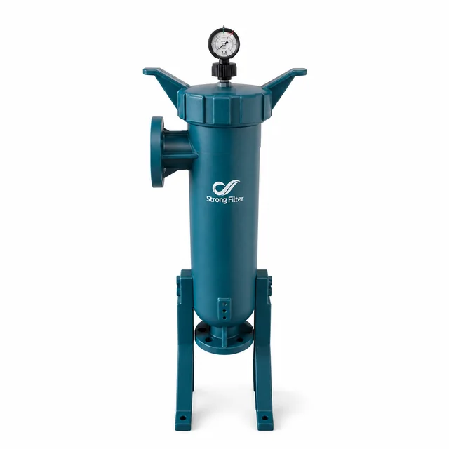 PBV
The gallery shows different views and construction details from this series.
Product overview
A screw-on cover and plastic housing simplify routine access, with PPH as a material direction to review against the fluid.
- Series
- PBV
- Selection priorities
- Fluid compatibility, body material, temperature, pressure, connections, installation space and maintenance
Working principle
PBV houses one filter bag in a plastic body. Fluid compatibility must cover the body, bag and seals.
Construction & flow path
The existing series description identifies a screw-on cover and PPH material direction. Confirm bag size, connections, pressure and temperature for the actual model.
Applications & filtration duty
A single-bag option where plastic wetted construction is required. Assess corrosion compatibility from the actual material and fluid.
Technical parameters
Use these specifications for selection. Materials, dimensions and operating conditions follow the selected model and agreed specification.
Materials & construction
- Body materials
One-piece homopolymer polypropylene (PPH) construction.
- Opening and cleaning construction
Screw-on cover; polished inner-wall design for cleaning access; reinforced internal plastic basket.
- Seal-material codes
V=fluoroelastomer; S=silicone rubber; select against the fluid and temperature.
Filtration specifications
- Bag configuration
One Size 5 bag.
Operation & maintenance
- Maximum operating temperature
<70°C; review against the actual fluid and seal material.
- Maximum operating pressure
0.7 MPa; this figure does not apply to every temperature and fluid condition.
- Water-flow reference
Water-flow reference: 15 m³/h. Determine actual capacity from the fluid, bag, temperature and allowable differential pressure.
- Fluid compatibility
Review acid/alkali type, concentration, temperature, exposure time and seal material; suitability is not universal for corrosive fluids.
Connections & installation
- Inlet and outlet sizes
DN40 / DN50 options; confirm connection standard and flange class against the model.
- Installation construction
Reinforced support frame; check mounting holes, overall dimensions and weight for the selected model and installation drawing.
- Flange-standard options
Chinese / US / Japanese / German flange-standard options; confirm the exact standard and class by model.
Configuration & supply scope
- Ordering structure
PBV15 - inlet/outlet size - seal material.
- Application directions
Fine chemicals / biochemical products / biopharmaceuticals / environmental processing / electronics / electroplating / dyeing and printing / paper / industrial wastewater / desalination; review the actual fluid and process.
Associated bag parameters
These specifications and service conditions belong to the associated elements; review compatibility with the specific housing and duty.
Materials & construction
- Associated bag materials
PP=polypropylene; PE=polyester; NMO=nylon monofilament.
Filtration specifications
- Associated bag rating
Filtration rating follows the selected bag; specify media, rating and rating basis when ordering.
Configuration & supply scope
- Associated bag seam codes
S=sewn; WE=thermally welded.
Model and configuration notes
PBV + bag quantity/size + connection or custom fieldsPBV identifies the plastic bag-housing family; complete numeric and version fields require document review.
Nozzle layout reference 1–15
Compare inlet and outlet directions to plan the connection to your pipework.
Opposite sides · level
Side in · bottom out
Side in · right elbow
Twin bottom ports
Bottom in · upper right
Opposite sides · high to low
Bottom in · upper left
Same side · high to low
Top in · bottom out
Top in · left elbow
Top in · lower right
Side in · return pipe
With return pipeOutlet defined by designRight in · bottom out
With return pipeSide in · lower left
With return pipeSide in · left elbow
With return pipe
Information to prepare for an inquiry
Use this family’s selection priorities to share available operating conditions, equipment information or drawings.
- Provide concentration, temperature and cleaner composition.
- Provide the required bag size, connections, operating pressure and temperature to review the configuration.
- Describe pipe support and housing installation.
Operation & maintenance
Before opening, replacing elements or disassembly, stop and isolate under the equipment procedure, depressurize, drain and confirm zero pressure. Inspect cover threads, plastic surfaces, seals and piping loads. Follow the model's tightening procedure and avoid excessive force.
Common operating inputs
- Fluid and major composition
- Target flow and operating pattern
- Operating temperature and pressure
- Contaminant form and target rating
- Material, connection and space constraints
- Maintenance frequency and existing equipment
Discuss this product’s configuration
Share the fluid, operating and installation conditions to review suitable specifications.
Products can be configured around the actual duty. Final specifications follow the quotation, drawing or technical agreement confirmed by both parties.
Related products
BV Flat-cover Single-bag Filter Housing
A straightforward flat-cover, multi-bolt construction for single-bag filtration with a clear operating sequence and layout choices.
Learn moreCBV Concave-cover Single-bag Filter Housing
The concave cover helps liquid settle back during opening, supporting a cleaner and more comfortable bag-change routine.
Learn moreTBV Convex-cover Single-bag Filter Housing
The convex cover provides another flow and opening arrangement for a single-bag housing, helping the design follow site pipework.
Learn more