
MCV Multi-cartridge Filter Housing
Multiple cartridges in parallel make it easier to scale filtration area and throughput around cartridge count, length and connections.
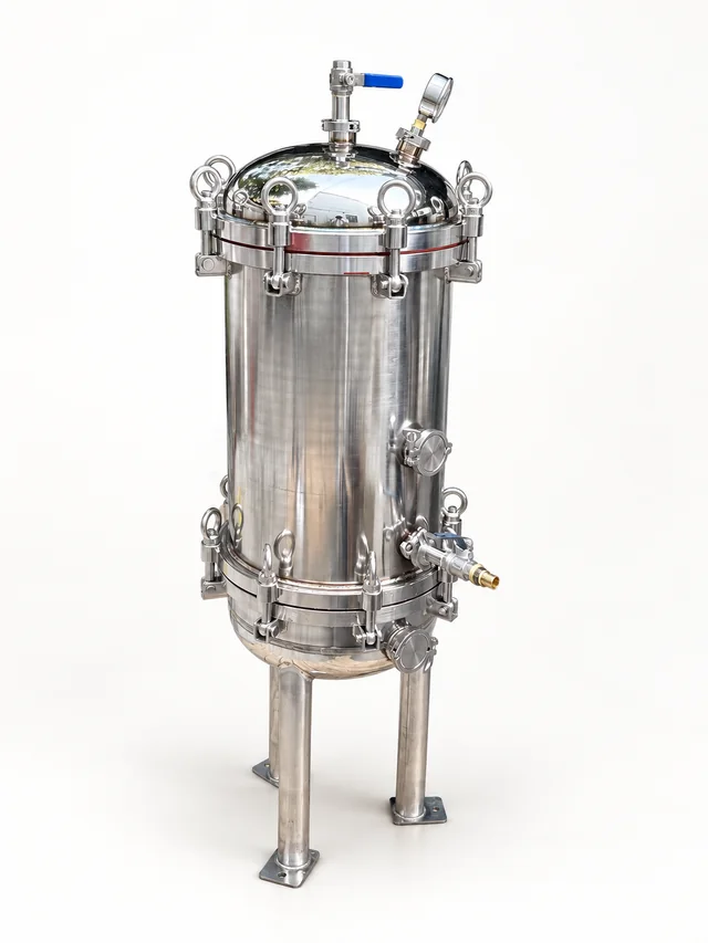 MCV
The gallery shows different views and construction details from this series.
Product overview
The MCV multi-cartridge housing can be configured around cartridge count, length, body material, pressure field and connection orientation.
Multiple cartridges in parallel make it easier to scale filtration area and throughput around cartridge count, length and connections.
- Series
- MCV
- Selection priorities
- Fluid compatibility, body material, temperature, pressure, connections, installation space and maintenance
Working principle
MCV runs multiple cartridges in parallel, sizing filtration area by count and length. Media selection determines the capture mechanism.
Construction & flow path
Match cartridge seats to the body, cover and wetted seals. Review count, length, interfaces and flow orientation within one configuration.
Applications & filtration duty
For process liquids, circulating loops and larger filtration duties. Liquid-cooling applications require their own fluid and particle-control review.
Technical parameters
Use these specifications for selection. Materials, dimensions and operating conditions follow the selected model and agreed specification.
Materials & construction
- Body materials
304 / 316 stainless steel; specially specified materials require model confirmation.
Filtration specifications
- Filtration rating
Determined by the installed cartridge; the housing has no independent filtration rating. Confirm cartridge-to-housing compatibility.
- Cartridge quantity
1–88 cartridges; follow the specific model and approved drawing.
- Compatible cartridge lengths
Conventional cartridge lengths of 9.75–40 in.
Operation & maintenance
- Design-pressure range
7–21 Bar options; this range is not the operating pressure of every current model.
- Flow selection conditions
Determine capacity from the selected cartridge, fluid viscosity, temperature and allowable differential pressure; the housing alone does not define a universal rated flow.
Connections & installation
- Compatible cartridge diameters
28 mm ID; OD up to 70 mm. Check end fitting, compression and seal for the specific cartridge.
Configuration & supply scope
- Ordering fields
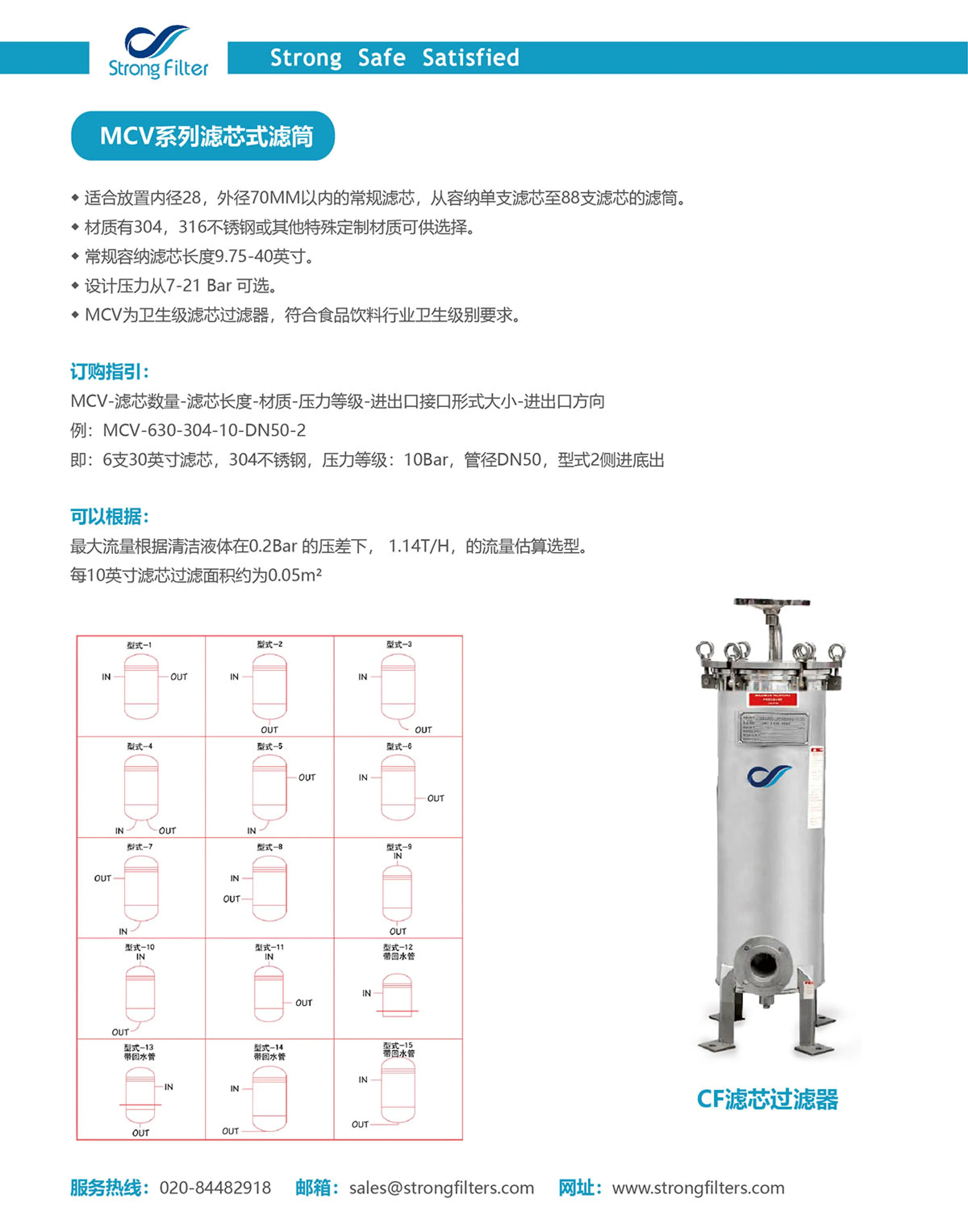
MCV / cartridge quantity / cartridge length / body material / pressure grade / inlet-outlet connection type and size / flow orientation.
- Ordering example and fields
MCV-630-304-10-DN50-2: six 30-in cartridges / 304 / 10 Bar grade / DN50 / layout 2, side-in / bottom-out.
- Nozzle layouts
Layouts 1–15; confirm inlet-outlet direction and return-pipe configuration against the approved drawing.
- Compatibility review
For integration or replacement, provide the full nameplate, cartridge model and installation drawing to check housing and element compatibility.
Associated cartridge parameters
These specifications and service conditions belong to the associated elements; review compatibility with the specific housing and duty.
Filtration specifications
- Associated cartridge area reference
Approximately 0.05 m² per 10-in conventional cartridge; actual area depends on cartridge construction, not the housing.
Selection information
- Operating temperature, operating pressure, seal grade and hygienic documentation
Model and configuration notes
Series + cartridge quantity/length + material + pressure-grade field + connection + nozzle layoutThe ending digits are first matched to 10 / 20 / 30 / 40-inch length, with the preceding digits indicating cartridge quantity; each series remains document-specific.
Nozzle layout reference 1–15
Compare inlet and outlet directions to plan the connection to your pipework.
Opposite sides · level
Side in · bottom out
Side in · right elbow
Twin bottom ports
Bottom in · upper right
Opposite sides · high to low
Bottom in · upper left
Same side · high to low
Top in · bottom out
Top in · left elbow
Top in · lower right
Side in · return pipe
With return pipeOutlet defined by designRight in · bottom out
With return pipeSide in · lower left
With return pipeSide in · left elbow
With return pipe
View the product sheetReview specifications, ordering options and construction diagrams for your application.
Information to prepare for an inquiry
Use this family’s selection priorities to share available operating conditions, equipment information or drawings.
- Size count and length around fluid, flow, rating and pressure loss.
- Check cartridge diameter, ends and seat.
- Separate housing design pressure from element differential-pressure limits.
Operation & maintenance
Before opening, replacing elements or disassembly, stop and isolate under the equipment procedure, depressurize, drain and confirm zero pressure. Record housing pressure drop and maintain consistent element specifications. Inspect each seat and retainer, allowing full-length element removal.
Common operating inputs
- Fluid and major composition
- Target flow and operating pattern
- Operating temperature and pressure
- Contaminant form and target rating
- Material, connection and space constraints
- Maintenance frequency and existing equipment
Discuss this product’s configuration
Share the fluid, operating and installation conditions to review suitable specifications.
Products can be configured around the actual duty. Final specifications follow the quotation, drawing or technical agreement confirmed by both parties.
Related products
PCV Plastic Cartridge Filter Housing
A compact PP single-cartridge housing for lower-flow liquid duties, configured around length, connections and seals.
Learn moreSCV Single-cartridge Filter Housing
A compact single-cartridge housing that can be configured clearly around cartridge length, connections and installation space.
Learn more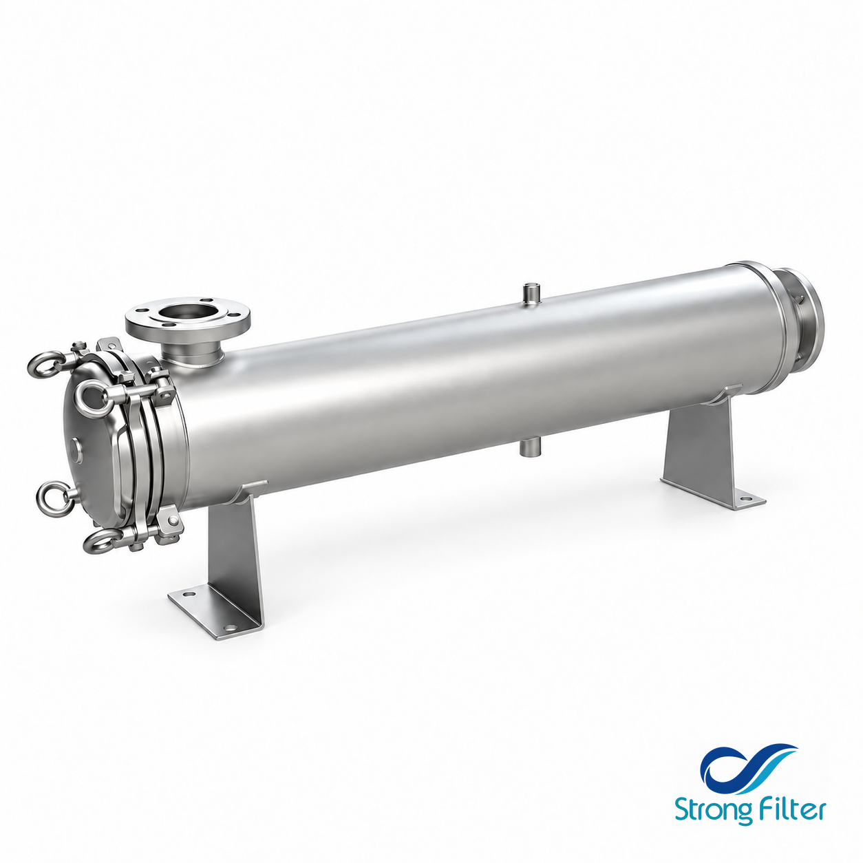
High-flow cartridge housings
A housing for high-flow cartridges, reviewed by cartridge interface, count, length and installation.
Learn more